|
Business Plan - Table of Contents

|
|
Disclaimer
ALL INFORMATION CONTAINED HEREIN IS INHERENTLY FORWARD-LOOKING AND REPRESENTS A PREDICTION OF FUTURE EVENTS AND ASSUMPTIONS WHICH MAY OR MAY NOT OCCUR. THIS FORWARD-LOOKING INFORMATION INVOLVES KNOWN AND UNKNOWN RISK, UNCERTAINTIES AND OTHER FACTORS THAT MAY CAUSE ACTUAL RESULTS TO DIFFER MATERIALLY FRON ANY FUTURE RESULTS EXPRESSED OR IMPLIED HERIN AND MAY NOT AND SHOULD NOT BE RELIED UPON TO INDICATE ACTUAL RESULTS OR RETURNS WHICH MIGHT BE OBTAINED.
|
|
Iceberg Capture, Attachment, and Towing
Overview
In summary, we will inventory target icebergs using commercially available satellite technology and tow them to an assembly point. After the startup phase of towing one target iceberg successfully, the icebergs may be prepared for being tethered one behind the other in a fashion similar to towing large barges, behind an appropriate towing vessel or vessels. The procedures for capturing and transporting icebergs have been well studied by prestigious scientific and engineering organizations (Rand, Weeks, etc.)
During the Concept development phase, ProvidIce will assess two key variables: individual icebergs vs. “trains” of icebergs, and single towing vessel vs. multiple connected towing vessels. In the subsequent section titled “Technical Data and Calculations” we develop water volume and shaft horsepower requirements for
a single target iceberg. However, there are many variables and tradeoffs associated with a final optimum configuration.
The overwhelming conclusions of prior studies were that this project is technically feasible and the economic outlook was positive when the primary commercial value is high quality potable water. We are building on these past investigations to establish the additional engineering and testing required to solidify the economic basis of both the system improvements and additional commercial products. These past studies substantially overlooked the economic value of cold water.
General Concept and Approach
The technical details and economic analyses of this project rely partially on previous work done by the Rand Corporation and the Ames Conference, discussed above. Our program, in its initial stages, will rely principally upon standard and available technology applied to relatively small iceberg trains or a target iceberg of size, supplemented, however, by patentable or otherwise protectable intellectual property.
 The deployment of the simplest and best developed technology that is available at this time implies conclusions that: The deployment of the simplest and best developed technology that is available at this time implies conclusions that:
The prototype iceberg will be profitable,
The initial iceberg train will be profitable,
The initial iceberg towing will begin within a reasonably short time frame of about 24 months following funding,
The long range plan of large, multiple iceberg trains with a very significant global impact will be operational in 36-48 month following funding,
The entire planning and implementation process is designed to put us in a position that appears invulnerable to potential competitors.
Our initial analysis will explore the practicality and need for “iceberg trains”. In addition to technical considerations, the need for trains will be dictated by customers, water volume requirements, towing distance, destination locations, iceberg size and form, and other factors.
We emphasize the relative simplicity of our approach for the initial iceberg. While we suggest certain improvements or innovations, these are based upon the applications of existing technology rather than new theories that need to be elaborated and tested at a scientific level as opposed to a rapidly implementable engineering level.
It is our intention to rapidly enter the market in a manner that is practical and with a minimum of innovation. The timing is perfect given the long term drought in southeastern Australia and southwestern United States.
This is to insure:
(1) generating revenue and profit as soon as is reasonable,
(2) proving the technical and business aspects of iceberg utilization on a commercially significant scale with one or more icebergs, and
(3) to cement our place as the primary practitioner of the technology in the eyes of both potential new customers as well as potential competitors.
Each target iceberg or iceberg train should have a minimum deliverable estimated economic value of $100 million for water and $90 million for the power component, plus to be determined emissions offsets.
The overall plan is summarized here. Target Icebergs in the Antarctic, depending where our customers are located, will be spotted using existed satellite technology, inventoried, and evaluated by satellite surveillance technology that is well established and available commercially. Icebergs most suitable for our use, based on size, shape, accessibility, and location will be identified and tracked. Prior to cabling or roping the iceberg, side scan radar will be used to confirm the configuration and its suitability for towing. On site analysis will confirm this, perhaps with seismology and other existing technologies. Conventional tug boats or other vessels will move them to an appropriate assembly point, in the summer months, where they will be attached or coupled to each other and tied to the transport system. Insulation, intended to minimize melting of the icebergs during transport, will be applied by wrapping them with plastic film, or foam, as discussed below, if needed. Insulation will be needed primarily on long-haul deliveries and will be avoided on short-haul deliveries in most cases.
The selection and harvesting of icebergs must be correlated with weather patterns. The time of year when free icebergs are accessible, and the supply and location at that time, must be predictable so that the enterprise can depend upon the source of supply. The newer weather and environmental satellites provide a valuable means for continuous survey of the iceberg resources.
In order to provide a year-round supply, so that towing vessels can be fully utilized, some means of storage must be utilized, preferably in the ocean with very cold water, minimum current, and free from pack ice. Thus, oceanographic research will be an aspect of the initial work program.

Development of Iceberg Capture and Attachment Systems
The method of harvesting and attaching a target iceberg or the components of an iceberg train depends greatly upon the method used for transport. Some special skills and techniques will have to be developed for the transport system. Maintaining a fleet of ships for operation in Antarctic waters is far from routine. An important safety factor would be the inclusion of an ice-breaker in the fleet, to prevent losses from inadvertent entrapment in pack ice at certain times of the year.
We anticipate the iceberg capture sequence would occur in the Antarctic summer months, generally October through March of the calendar year. Temperature and wind conditions are much more compatible during this period for marine operations. We estimate that for much of this period temperatures will be in the range of zero degrees Celsius in the offshore seas where the icebergs will be harvested.
The design of the transport system requires optimization of many factors. Fuel costs of
higher towing speeds must be reconciled against capital costs; ice/water loss is a complex function of water/air temperature and must be optimized. Fixed cost of staffing (both tow and management) must be considered. An optimized solution must take into account the size and extent of the market relative to the formidable economics of very large scale. A particular opportunity to be optimized is making the delivery system compatible with the proposed means of utilizing the latent heat and water within an iceberg. Because the tradeoff between energy and water usage depend strongly upon customer requirements, there is a need for a highly interactive phase of the design for the overall system in order to match end user needs to both water supply and the cooling energy.
The most reliable and economical source of transport energy would be nuclear power. This energy source is dominated by capital costs rather then fuel costs. Its use would be associated with transport and consequent lower capital and carbon footprint costs for vessels, etc. This is why the project team is initiating dialogue with a marine services firm that has the required nuclear powered ships in civilian inventory. To make year-round delivery of icebergs from intermediate storage points to points of end use will be a formidable undertaking. It will require utilization of the most contemporary developments in marine technology, including most current oceanographic data on ocean currents, winds, temperatures, and technology such as satellite weather maps, electronic navigation systems, and special warning systems to prevent collisions on the high seas, particularly in or near major shipping lanes.
Development of Iceberg Transportation Systems
In brief, icebergs will be gathered one at a time and when appropriate, may be tethered, one behind the other in the fashion of barges, behind a towing vessel, and/or utilizing tugs, with sufficient shaft horsepower to tow or propel whatever number of icebergs and correlated mass has been determined to satisfy outstanding contract(s) for delivery. The two earlier Rand studies, and the proceedings of the First International Conference on Iceberg Utilization, listed above and cited in full in the footnotes, discuss much necessary material in detail, such as mathematical analysis of the relationships between iceberg dimensions, propelling force and trip time over selected routes all as a function of the many parameters that are involved. Such parameters include length of trip cycle, timing of iceberg acquisitions during Antarctica daylight thawing seasons from October through March, transit times, drift currents, transit speeds, wind directions, wind speeds, wind directions, wind force (both normal and peak/storm), ocean currents described by magnitude and direction, and Coriolis and drag force effects. The RAND reports estimate a towing speed of about two knots. Additionally, Banks has also done an Independent analysis and has developed an optimum towing speed of about two knots.
Preliminary mass and propulsion calculations have been completed for proposed systems capable of generating adequate thrust. Additional work will be done to maximize the use of ocean currents. Also, other forms of wind energy will be evaluated. These include Beluga Group Sky Sails (See belugagroup.com, successfully tested in March of 2008) or fixed sails mounted on the icebergs or a combination of such alternatives. These calculations and the different market opportunities they represent in terms of an individual iceberg or multiple icebergs of train size are incorporated into the Technical Data and Calculations section. The additional effect of adding synchronized aluminum sails on an iceberg train has not been previously considered or analyzed. This new concept will be tested in the mathematical model. The Rand studies also determined the need to proceed in two steps: an initial train where two or three relatively small icebergs are transported to the point of use on a commercially profitable basis, and a full large-scale commercial phase where a single transport could include a greater number of substantially larger icebergs in longer trains. Similarly, it may be advantageous to use multiple small trains to varying destinations, rather than one large train. To go from one to the other is an evolutionary process driven by the market itself. Below, we compare the large train concept with assembly of a number of smaller trains as the market is developed - train size must inherently be driven by signed contracts for delivery of icebergs and resulting products on a profitable basis from inception.
To add some context to the estimated horsepower requirements needed to tow one target iceberg, past studies provide initial guidance (Hult & Ostrander, 1973; Banks, 1998). About 140,000 shaft horsepower is needed for towing at about 2 knots per hour of 1200 meters long x 400 meters wide x 200 meters thick. (Banks, 1998). Battleships of the Iowa class have about 212,000 shaft horsepower. Thus large modern vessels or leased retired military vessels appear to be well within the required towing range. Some of the largest icebreakers in the world are Russian built nuclear powered ships; some are available in the Russian civilian fleet. However, power is only one consideration is establishing optimal towing speed. Fuel consumption, ablation, cost of capital, and other considerations will be evaluated in establishing optimal towing speed.
The primary reason for utilizing icebergs from Antarctica is the fact that that they calve or break away from the glaciers in a large rectilinear or blocky shape. In the Arctic, the icebergs are smaller and the glaciers calve in highly irregular shapes, making them difficult to capture and tow.
Additional areas to be addressed as part of the issues of capture and delivery are ablation (melt loss), insulation, mass loss due to sea water temperatures and hydraulic friction in transit. The Rand study recommends the full insulation of the underside of each iceberg for long haul situations - the means of doing this should present additional intellectual property concepts worthy of protection given the size, depths, variations, and other issues which present, if this indeed proves necessary. For example, a Teflon quilt like material might be used. However, no patent search has been done and patent counsel is yet to be consulted. We shall run computer modeling to see if insulation can be limited or avoided by the use of insulating collars and/or other techniques, still preserving profitable operations when icebergs are delivered, depending on trip length. Weather issues appear capable of relative long range forecasting by satellite. Coriolis effects need additional modeling and study, although they are significantly addressed by Rand and others and in general are judged to be of minor import.
Certain components of the Rand studies need further work and certain aspects involving the intellectual property involved here need further development and legal protection. Certain additions are considered to the Rand studies and the Ames Proceedings (principally involving improvements in towing, terminal facilities, and processing including creation of the ice/water slurry for use in central chiller systems).
Development of Iceberg Mooring/Processing Systems
At each location where ice is to be delivered, a suitable receiving system must be designed and constructed. Depending upon end-user needs and geography and oceanography, alternatives include a lagoon, a graving dock, a lock of some type, or deep water mooring systems. The receiving system will have to successfully interface with both the transport system and the final uses of the ice, water, and latent heat of the ice slurry. The transport vehicles must be capable of unloading or decoupling its shipment promptly and allowed to resume service, as it represents both a capital and operational loss when it is not moving. The end use system, on the other hand, must include some kind of storage, either in the receiving system itself or elsewhere, so that year-round continuity of water supply is feasible.
The initial trains will consist of two to six icebergs. The overall dimensions of the initial two iceberg train will be about 3,000' long (allows 1,000 feet between icebergs) X 1500' wide by 1,000' thick. About 85-90 percent of iceberg height will be under water. Towing vessels, conventional tugs or nuclear powered vessels will transport the initial trains to targeted markets. Several auxiliary ships accompanying the train will carry supplies, apply insulation en-route as well as during train assembly, if needed, and provide other support services.
When the target iceberg(s) reaches a customer location, one or more icebergs will be dropped off and moored offshore. The transport system will then move to the next market to drop other icebergs, if in a train. The iceberg(s) dropped in a given market will be processed by various cutting, grinding, and melting techniques. An ice slurry in fresh water will be piped ashore to wholesale terminals and utilization complexes, which constitute the final delivery points for the initial primary iceberg products.
Once an iceberg train has arrived at its destination processing will commence by delivering the cutter/crusher processing system onto the iceberg by heavy lift helicopter or dirigible. The cutter/crusher will carve a sump area in the iceberg, similar to a volcanic cone. A pumping system with a submerged pipeline will facilitate on-shore delivery.
The ice slurry has an enormous heat exchange capability, which shall replace a large amount of electrical generating capacity when used for air conditioning or other cooling purposes in large metropolitan and industrial areas. Direct power generation using a working fluid and the heat differential of the ambient ocean water and the ice slurry may also be developed depending upon local needs. This application is facilitated if there is an available central hot water or steam heating system that could be used for conveyance of chilled water in the summer. (Downtown Denver, Colorado, USA utilizes such a system.) If no system exists, it will need to be constructed by the customer, if desired. Once the water temperature of the cooling water has been raised after passing through heat exchangers it will be blended with or added to existing water supplies to provide its water supply functions.
Generally there is stronger opposition to building new ice processing facilities on-shore. Our concept is to attach an ice slurry pipeline to a pipeline riser attached to a large docking buoy. The slurry would then be pumped through a pipeline on the ocean floor. This facility would be located sufficiently offshore in appropriate water depth. Also, the iceberg may modify local weather conditions by creating fogging. This question will be addressed by a climatologic model to assess the site specific, meteorological conditions and the impact of the iceberg on the range of conditions anticipated. This "iceberg slurry bridge" will convey the ice-water slurry to the end user dockside. The end user will handle all of the land-based distribution of the product. Appropriate meters will be integrated into the delivery system, so water volume plus quantity delivered and the temperature of the product can be measured, leading to initialization of final payments.
Depending on where the iceberg is delivered, appropriate environmental impact studies consistent with local regulatory infrastructure for deepwater port permitting will have to be obtained.
We plan to piggyback on the activities of the deep water terminals developed in the liquid natural gas (LNG) industry. Houston based Aker-Kvaevner is a leader in this area. Also, Fluor Corporation, Aliso Viejo, California, is a leader for the engineering, procurement, and construction management of large terminal facilities. We intend to discuss our concepts with them and current plans are to retain the firms in Phase One.
We anticipate the general docking buoy will be anchored to the seabed with a cabling/anchor system. The docking buoy will be connected to the subsea pipeline and to shore through a flexible riser system. The pipeline may be buried or could be placed on the ocean floor, appropriately ballasted and anchored, or could be 100 to 200 feet below the surface. These types of installation are common and employ standard technologywith flexible piping up to about twelve feet in diameter. An installation rate has been reported at about 1.5 miles per day.
Potential Improvements to the Basic Technical Plan
The primary areas to be studied for Phase I relate to iceberg coupling, iceberg towing, and iceberg insulation.
This is because these are important cost and technical areas that need to be optimized, and because it is believed that significant improvements can be made relatively soon. These three areas are discussed below.
1) Iceberg coupling – It appears that the simplest towing harness could be a towing configuration consisting of three members or sections: (i) a floating member, (ii) an elastic member, and (iii) a submerged member. The first (floating) member is load bearing and otherwise similar to the towing hawser presently used (2000 feet of positively buoyant polypropylene 3-4” rope). The second, non-load bearing component, with its special expansion or fuse properties, ensures proper static and dynamic loading of the other two members. The third section constitutes the critical load bearing element. Constructed from slightly negatively buoyant material, this section applies the steady state sub-surface towing force while minimizing rotational torque. We would plan to use a carbon fiber rope system for larger icebergs.
The three members are connected by a shackle and swivel assembly. The overall configuration is similar to that shown in Figure 1 from C. Peter Benedict’s A Study of Iceberg Detection for Marine Navigation.
2) Iceberg propulsion - Kites (such as those made by Belugia Group and Sky Sails www.beluga-group.com) or sails attached to each iceberg have the potential to save significant quantities of fuel when wind conditions are appropriate (10-15% of fuel costs), as compared to the sole uses of towing vessels and/or electrically driven propellers at all times. An evaluation of this approach will be made by studying the following aspects of sail utilization: sail design for the best fuel saving performance; sail structure strength based on expected winds along the delivery routes; evaluation of software and hardware for real time control of sail settings, and for taking in and letting out sails; analysis of Beluga Group Sky Sails (See beluga-group.com); and a computerized analysis of the costs and benefits of using sails, based on the likely wind patterns to be encountered.
3) Iceberg insulation -- This a high priority area for development of better technology, based on the highest potential return expressed as both lower costs and simplified technology. The two questions to be answered are: Is insulation really necessary, particularly for the short haul concept?
And, if yes, what is the best way to do it?
The Rand analysis strongly demonstrates that insulation is needed for long hauls, and we believe their conclusion will ultimately prevail. Additionally it may be cost effective to attach a preformed bow to the lead iceberg to cut drag. Also, it may be feasible to include nitrogen cooling coils in the bow area to keep the mass solidly frozen, maintaining its integrity. (Banks, however, calculates only a 10% loss with no insulation on short hauls). The Ames Proceedings extensively discusses insulation, with an emphasis on foam. Contact has been made with the foam industry trade association and discussions are being initiated with firms learned and experienced in the art of sub-marine foam application. The Rand recommendation for insulating technology appears to be well thought out and to be doable, but it is complex, time consuming and expensive. This project will evaluate other approaches with the objectives of simplifying the insulation procedure, and reducing the costs and time of insulating for those trips which would necessitate insulation.
If it appears to be warranted, one of the icebergs in the initial train may be left un-insulated, or insulated in a different manner, to provide quantitative results of the value of each approach.
Figure 1
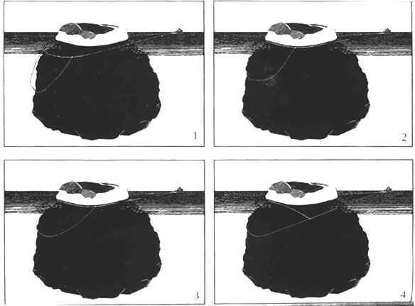
A Study of Iceberg Detection for Marine Navigation, C. Peter Benedict – Figures 1 - 4
This configuration overcomes the adaptability problem common to all systems that use tow or more parallel load bearing members at the same time. Such geometries depend on load distributions that cannot be assured because of the unknown iceberg geometry, especially the below water shape.
During initial deployment and at the initial point in the tow, before any load is applied, the load section hangs loosely below the rear of the berg, as shown in Figure 1. As the load is first applied, it is transmitted at the waterline only (see Figure 2). The expanding member extends freely, bringing the load section taut around the submerged portion (Figure 3). Immediately as the load member catches the aft surface, it applies the full towing fore (Figure 4). If, in the unlikely event that upon first application the load unit does not catch and rises to the surface, the load is reduced, allowing the expanding member to contract and replace the load member below the surface. This process is repeated until the full load is applied by the lower member.
Icebergs of widely varying cross-section can be accommodated by proportionally increasing the lengths of the expandable and load sections. It is not necessary to add additional parallel members which would make the system difficult to handle. Operationally, on the ship, this means that “special sections” will be laid out on deck perpendicular to the polypropylene lengths. On the basis of the above and below water shape, and using specially fabricated shackles, the sections are clipped into the center point of the polypropylene section. Since the towing problem arises for smaller domed and quasi-stable bergs, tow fuse sections would seem sufficient.
This proposed towing configuration combines three essential characteristics required for a successful improvement over existing towing equipment and procedures. These are: deployability (ease of handling before, during, and after deployment), adaptability (to the full range of iceberg sizes) and compatibility (with the existing equipment and procedure).
Alternative towing concepts will be modeled in our proposed hydrodynamic activities to select the optimum configuration.
Other alternatives include placing a carbon fiber net arrangement around the iceberg. This would be similar to a hairnet around a piece of ice. The spacing of carbon fiber rope would be about two hundred feet running both laterally and longitudinally around the entire iceberg. A remotely operated vehicle would be used for underwater placement.
Towing Swivels or universal joints would be utilized between icebergs and the towing vessel to allow for individual iceberg rotation enroute, as well as safety swivel back ups utilizing explosive bolts for rapid emergency decoupling while under load if need be.
Related to coupling is the need for software for dynamic and static load analysis, carbon fiber netting placement, anchor placement and force analysis of the towing mechanisms on an iceberg both in-situ and while under dynamic towing loads. Such software should be capable of modeling acceleration, deceleration, stability, force analysis and dispersion of force analysis, current impact, ablation impact, force dispersal analysis of anchors, ice density and ice strength. Attention to these areas shall maximize the quality and quantity of ice delivered on site.
Mooring the Iceberg
The very high forces involved in towing and mooring icebergs probably call for use of the strongest available lines. High strength carbon rope is available in diameters of up to 3 inches with nominal breaking strength at this maximum size of about 1,000 tons. The maximum working tension for design purposes should be about one-third the nominal breaking strength.
Conventional drag embedment anchors provide horizontal resistance by digging into seabed sediments. Such conventional anchors, as well as other designs and systems are regularly used to moor and stabilize off-shore drilling platforms and oil off-loading systems. (The largest offshore towing platforms include the Eirik Raude at 53,000+ tons and Thunderhorse at 60,000 tons. Both can work in 10,000 feet locations). Resistance is dependent on anchor design, properties of the bed, depth of embedment, and length of drag. Suitable anchoring will be an important component of the system design.
Iceberg Processing
To utilize the melt water there is a menu of techniques, selection from which will be driven by the desires and needs of a particular customer. To capture the melt water from the exterior of the iceberg, a floating barrier or skirt can be constructed around the perimeter. Wave deflectors can cap the skirt to protect the product water. This barrier will trap the melt water since it is lighter than sea water. Exterior to the skirt, a plastic Styrofoam layer may be placed on the sea water to dampen wave action. A floating pump system can be placed in this fresh water reservoir with the water being pumped to the shore in a submerged pipeline for distribution. The iceberg can be covered with a Teflon or other fabric material that is silver for solar reflectivity on one side and black for solar absorption on the other side. In this way, the rate of ice melt can be regulated as a function of demand. Additionally, the melt water will be protected from pollution by sea birds. This technique is a fairly passive technique with certain management options for the purchaser being present that are not necessarily present with other alternatives that can be used by other owners with different management philosophies with respect to both the water and power being purchased.
Another means for processing the iceberg is to tow it to the end user and break it into manageable sizes. A large dry dock can be utilized for processing. The fractured iceberg pieces could be towed into the submerged dry dock with the salt water pumped out of the dry dock walls, raising the iceberg and then pumping the salt water out of the interior of the dry dock before processing begins. The ice in the dry dock may be shredded by large overhead industrial cutting wheels. The product water/ice slurry will be pumped to the end user from the dry dock. The processing dry dock may be about 1000 feet long and 500 feet wide. This is typical for dry docks currently used for large cruise ships.
Depending upon the customers' needs, another means of accomplishing this is to build a large semi-submersible dry-dock. The iceberg could be delivered to the port and there be broken by blasting into desired pieces to be placed in the dry dock. To keep the broken pieces of ice together, prior to blasting the iceberg would be surrounded by a large circular boom.
Depending upon the customers' needs, the iceberg could be processed or quarried in-situ at the mooring site by using modified equipment from the coal mining industry. A large chipper system with a movable head would excavate a depression or sump in the iceberg. The chipper would move around the sump in a circular fashion (creating a depression like that of the cone of a volcano) letting the water and ice chips accumulate in the constructed bowl.
From there the ice slurry would be pumped on-shore through submerged pipe for security and avoidance of shipping interference. If shipping interference is not an issue the delivery pipe could be designed to float.
Regardless of the individual technique used for a given customer, an ice-water slurry or cold ice water will be received by a terminal receiving system on-shore which shall store and pump the slurry to heat exchangers for utilizing the enormous cooling capacity initially (i.e. a form of power production/substitution) and then delivered to existing water storage reservoirs, or injected into underground aquifers for multiple market purposes such as replenishing well water or to control salt water incursions into coastal aquifers which can also be undertaken to profitable advantage.
If delivering multiple icebergs in a train, the iceberg train would be delivered to various mooring facilities along coastal areas. The train would drop off icebergs depending on the orders received for water and cooling capacity among various population centers. The configuration of the mooring facility will be a function of the individual marine setting in terms of depth and currents.
For deep water, over 2000 feet, positioning tugboats with GPS devices would be used to keep the iceberg under control. (Due to costs and the loose anticipated tolerances, a complete dynamic positioning system should be evaluated, but will probably be more costly and therefore not used). For shallower water cable mooring systems to the ocean floor would be utilized similar to remote off-loading terminals currently used for oil tankers. Special provisions for maintaining the integrity of the mooring systems during storms, with resulting increased design load requirements, shall be built into the system.
The processing technology employed will be a function of the individual port setting, adjacent land topology, and local customer preferences. There are many possible ice processing techniques. Appropriate engineering/environmental and cost studies must be conducted to match the best technology to each customer's area, using current, standard technologies.
Protecting Iceberg Water Quality
The iceberg melt water has a total dissolved solid (TDS) content of less than 100 milligrams/liter (mg/l). This is an extremely high water quality that could be used for blending with brackish water to increase the potable supplies of a region. The Federal EPA safe drinking water standard for potable supplies is 500 mg/l. However, much of Southern California obtains its water from the lower Colorado River that has a 750 to 800 mg/l TDS content. Many of the water purveyors are planning highly energy intensive nano-filtration systems in order to reduce the salt level and bring this water supply into compliance. The blended high quality melt water would serve the same purpose and at a lower anticipated cost.
Protection of the inherent high quality potable water in an iceberg will be dictated by the processing techniques used by a given customer as well as the precise technology a given customer may choose to employ for the heat-exchange mechanism to extract the "coldness" from the iceberg in the electrical power cycle component of the product. This is simply an area that will have to be attended to on a customer by customer basis. Some of the work will be done by us, but most of it will be the responsibility of the customer and any joint venture partners of the customer in the destination infra-structure used for processing.
Technical Data and Calculations
Realizing that those with a technical orientation will require analytical rigor, we provide
calculations and analysis relative to the following key aspects of this plan:
Iceberg water quantity
Iceberg thermal cooling energy
Required power to tow an iceberg
Carbon offset value
Summary Revenue pro forma Calculations
While icebergs vary dramatically in size and shape, we have chosen a reference iceberg with dimensions of 3000 ft. x 1500 ft. with a depth of 1000 ft. This is well within the range of typical iceberg size and there are an abundance of target icebergs in this size range.
Iceberg Water Quantity
Calculations
3000’ x 1500’ x 1000’ = 4.5 billion cubic feet of water
One cubic foot = 7.48 gallons (standard conversion)
4.5 billion cubic feet = 33.7 billion gallons
One acre foot of water = 325,851 gallons (standard conversion)
33.7 billion gallons = 103,306 acre feet
Results
Reference iceberg contain about 30 billion gallons of water. (Also about 103,000 acre feet of fresh water.) At a usage of about 150 gallons per person, per day, this serves over 500,000 people for a year.
Iceberg Thermal Cooling Energy
One BTU is defined as the energy associated with a one degree Fahrenheit temperature change in a pound of water. Further, it takes 144 BTUs of energy in transition from ice to a pound water at 32 degrees Fahrenheit, known as the latent heat of fusion. Thus, each pound of ice in an iceberg releases156 BTUs of thermal cooling energy in the transition from ice at 32 degrees Fahrenheit to water at 44 degrees Fahrenheit.
In water there are 62.38 pounds per cubic foot.
A target iceberg contains 4.5 billion cubic feet of water (see calculation above)
A target iceberg contains 281 billion pounds of water
Each pound releases 156 BTUs
BTUs of thermal cooling energy in target iceberg transition from ice at 32 degrees Fahrenheit to
water at 44 degrees Fahrenheit = 4.38 X10¹³ BTUs of Thermal Cooling Energy
Required Power to Tow an Iceberg
Towing vessels measure towing capacity in terms of shaft horsepower which is the power delivered to the vessel’s propeller shaft. In general, the term “horsepower” refers to work over time. Since the term “work” equates to force times distance, again in general terms, horsepower is equal to force times distance divided by a unit of time.
Now we turn to analysis of the shaft horsepower required to tow a target iceberg. In towing an iceberg there are two overall forces of resistance: water resistance for the portion of the iceberg below the waterline and air resistance for the portion of the iceberg above the waterline. For our purposes the air resistance is minimal and will be ignored.
Water resistance to towing is comprised of three components:
Form Drag – which can be thought of as the actual resistance produced by ocean water as the iceberg is towed at a given speed. Intuitively, towing at higher speeds requires displacing more ocean water in a given time interval and thus more “power”.
Skin Friction – which can be though of as the “rub” between ocean water and iceberg ice at the surface level.
Wave Resistance – which can be thought of as the variable resistance of waves as the “slap against the iceberg” at the ocean water surface line. In analytical terms the relative impact of wave resistance is a function of the overall object size (in this case iceberg size) and the size of the waves. Since our reference iceberg is large relative to the size of even the largest waves, wave resistance is negligible and will be ignored.
Technical Forum Signup >>
|
|
|
Technical Discussion >>
See Our Technical Information. Further discuss and add to the discussion of the specific, in depth issues involved. If you have technical expertise, contribute your thoughts - some of you will end up being strategic partners down the road.
Not a member - Forum sign up >> | |
|
Accredited Investor Sign Up >>
If you qualify as an Accredited Investor (and most of you who do already will know what that means), you can assess whether you wish to participate from a serious economic standpoint.
| |
|